|
|
||||||
|
|
|
|
Download | |||
Diamond Version 5 User Manual: Modes of operationOverview
This article is an overview about the different operational modes when working with a structure picture:
Previous article: Deriving new pictures Select and Edit modeThe Select and Edit mode is the default and regular working mode in a structure picture. The mouse shows an arrow pointer and you can click an atom or bond or label etc. to edit its properties or to choose it as starting point for a building operation or delete it etc. Besides the individual clicking (selecting) of single objects (like atoms), there are special options and commands for extended selection, e.g. by defining a rectangle or by defining a free-hand figure, called "lasso", to select all objects inside the rectangle or figure, rsp. You can use additive or subtractive selection to add clicked objects to the list of selected objects without destroying the selection states of other objects. And you can use the status keys Shift to add a selection by keeping the other objects' selection states and Ctrl to invert the selection state of a clicked object individually from other objects. This is described in detail in the article "Selecting objects". Tracking modeA tracking mode is a special mode where the structure picture follows the mouse movements simultaneously. This can be a rotation along x- and y-axis, a rotation along z-axis, a shift within the drawing area, enlargement or reducing, or a variation of the viewing distance (camera distance), or a movement into or through the structure picture ("walking in or out").
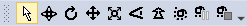
To enter one of the tracking modes, either push a button in the Move toolbar,
or use the corresponding command from the Move main menu:
In a tracking mode, the mouse cursor changes to a symbol made up of the standard arrow plus a symbol signing the mode of operation.
In this mode, you cannot select objects (like you can in the default Select and Edit mode, see above).
To return to the default Select and Edit mode, either push the The actual tracking starts when you press down the left mouse button and move the mouse. In this case, the mouse cursor symbol drops the arrow symbol and only shows the special symbol depending on the mode of operation. These symbols are identical with the symbols in the Move toolbar. To (temporarily) stop the rotation etc., simply release the mouse button, to continue it, press it down again. The tracking modes are described in more detail in the following articles:
Rotation along x- and y-axis, rotation along z-axis, and shifting
Enlarge or reduce, changing perspective impression
Moving into or through the structure picture The tracking modes also use a spin option where you can accelerate the speed of e.g. rotation and leave the structure picture rotating continuously when you release the mouse button. This is also described in the chapter "Rotating and Shifting the Structure" of the article "Orientation and Position". Grab modeThe "Grab mode" is an alternative to the above mentioned tracking modes, where you can rotate a structure picture with the left mouse button down or shift it with the right mouse button down or enlarge or reduce it with the mouse wheel and select objects. The "Grab mode" can be activated with the (here yellow highlighted) toolbar button or with the Grab Mode command in the Edit menu (the arrow symbol right beneath can be used to terminate the "Grab mode" and return to default "Select and Edit" mode):
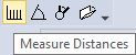
For details read the article "Grab mode". Exploration ViewWhereas the above mentioned modes change the mouse cursor and the behaviour how Diamond reacts on mouse movement and mouse clicks but stays in the regular Diamond Structure Picture Edit view, the "Exploration View" is a special mode and view where you can change special properties such as bonding spheres, contact spheres, H-bonds, and atomic environments. Unlike in the regular "Picture Edit view", the changes you make in the bonding or contact spheres in the "Exploration controller" window are directly reflected in the structure picture and vice versa. (In the regular view, you have to use modal dialog windows where you make several changes to bonding/contact spheres and then press OK and then check how good these new settings work.) On the other hand, most of the picture designing functions of the regular "Picture Edit view" are not available in the "Exploration view", which is due to the focus on studying bonding and contact spheres as well as H-bonds, The "Exploration View" is described in a separate series of articles: "Exploring bonding and contact spheres". Measuring modesThe measuring modes allow to interactively measure distances, angles, and torsion angles. You can measure interatomic distances by clicking two atoms each in the structure picture. The result is given in a yellowish info window and is stored in the list of reported distances and can be inspected later e.g. in the data sheet or in the table of reported distances. The measuring mode for angles measures the angle at the second of three clicked atoms each. The third measuring mode measures torsion angles between four atoms each. The measuring modes are available as commands from the Tools menu as well as from the Measure toolbar:
Details about measuring (and reporting) distances, angles, and torsion angles are in the article "Measuring and reporting distances, angles, and torsion angles". Another, more versatile measuring mode enables clicking an arbitrary number of atoms to measure angles between planes and/or lines as well as measure distances of atoms from a plane or line. This is described in the article "Extended geometric infos: Angles between planes etc.". Command-specific operational modesWhile for most of the commands in Diamond's Select and Edit mode you mark one or more objects (or no object to apply to all) and then run a command to build up a part of your structure picture or change a design, there are some commands that activate a special mode where you interactively work with the mouse, e.g. click or shift with one button pressed. These are described in more details in the corresponding articles:
Inserting bonds between two atoms each
Zooming a Rectangluar Area
Filling a rectangular area or a disk
Adding or removing polyhedron edges
Shifting or rotating a fragment
Viewing along an axis or towards a plane
Previous article: Deriving new pictures |
|
Page last modified September 14, 2023. Copyright © 2023 Crystal Impact GbR. All rights reserved. Contact Webmaster |