
|
|
||||||
|
|
|
|
Download | |||
Diamond Version 5 User Manual: Display of structure pictureRendered and flat representationThis article in brief:
Previous article: Destroying all or parts of the structure picture OverviewVersion 2 of Diamond introduced a new way of representing a structure picture producing high-quality graphics with shaded objects, transparency, material and light properties. This is called the "rendered representation", whereas the "old" standard representation, which is of course still available, is called "flat representation" in contrast. This article describes the differences between these two kinds of representation, their advantages and disadvantages, depending on the application of the picture or printout, as well as limitations. Rendered Representation: Features and Limitations
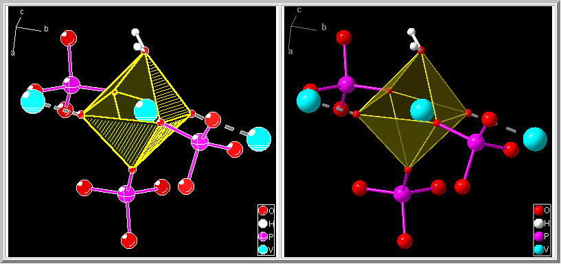
Diamond uses the MS Windows implementation of the OpenGL graphics library for rendered representation. This gives you a lot of possibilites to display photo-realistic shaded models with user-defined light sources, materials properties and optional transparency if wanted. Of course the common old-style drawing mode (the flat representation), which is more useful for black-on-white printouts, is also supported. The following illustration compares flat (left) and rendered (right) representation of the same structure picture:
The following table compares advantages and disadvantages of the two kinds of representation:
Switching Rendering On or Off
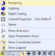
To change between flat and rendered representation, click on the (here yellow marked) Picture Settings button in the Picture toolbar: Alternatively, you can choose the Picture Settings command from the Display menu, and change the Rendering checkbox on the Representation page of the Picture Settings dialog.
Previous article: Destroying all or parts of the structure picture |
|
Page last modified August 17, 2022. Copyright © 2022 Crystal Impact GbR. All rights reserved. Contact Webmaster |
 .
. .
.