|
|
||||||
|
|
|
|
Download | |||
Diamond Version 5 User Manual: Display of structure pictureUnit cell vectors a, b, c, and atom vectors
In this article:
Previous article: Anti-aliasing Displaying the Unit Cell Axes
The three axes that define the base vectors of the unit cell, a, b, and c, can be displayed, if no cell edges are displayed.
To switch the display of the base vectors on or off, push the Picture Settings button
This option is also available in the Cell Edges Design dialog dialog: If the checkbox Show unit cell axes a, b, c is active, the unit cell base vectors a, b, and c are displayed.
Atom VectorsVectors can be assigned to atoms, e.g. to indicate a magnetic moment. You can define the vector components, length, position, color, line style and weight and more settings. The Atom Vectors command in the Objects menu opens the Add Atom Vectors dialog, if at least one atom is selected, or the Edit Atom Vector dialog, if no atom but at least one existing atom vector is selected. Here, you can either add a vector to the currently selected atom(s) or edit the properties of the selected vectors. An atom vector's direction is given by the three components u, v, and w along the axes of the crystal coordinate system. The length of the vector can be defined relatively or with an absolute Ångstroem value. Therefore clear or check, rsp., the checkbox Absolute length in the upper part of the dialog, in the Vector section. Besides this, the vector can have the origin in the center of the atom, i.e. it sits on top of the atom. Or the center of the vector is placed in the center of the atom. In this case, the origin of the vector will be on one side of the atom, while the peak will be on the other side. Choose From atom for the first, or Through atom for the second variant from the Position combo box. The radius of the shaft (cylinder) of the vector is given in Ångstroem and defined in the input field Radius. The other settings in the dialog define the color of both shaft and cone as well as an optional transparency (goes from 0 for opaque through 1 for complete transparency, which means invisibility). For flat mode representation, you can also define a border color and a border line style and line width. Changing atom vector properties after definition To change the style, color, or the length and/or direction of one or more existing atom vectors, mark the vector(s) as selected by clicking on the shaft or cone (in case of a "through atom vector" click on the upper part) and run the Atom Vectors command from the Objects menu. This will show the dialog entitled Edit Atom Vector(s). Adjust the settings where necessary and confirm with OK. Or use the Apply Now button to apply the changes but without closing the dialog window. Deleting an atom vector from the picture To delete one or more or all atom vectors from the structure picture, mark the atom vector(s) - not the atoms - and run the Atom Vectors command. In this case, a Destroy button is available in the bottom right of the dialog window.
Previous article: Anti-aliasing |
|
Page last modified September 25, 2023. Copyright © 2023 Crystal Impact GbR. All rights reserved. Contact Webmaster |
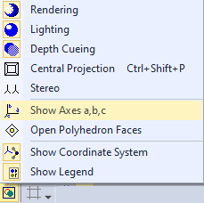
 in the Picture toolbar,
which opens a menu where you choose the Show Axes a,b,c command. (The icon is yellow, if the display of the axes a, b, c is activated):
in the Picture toolbar,
which opens a menu where you choose the Show Axes a,b,c command. (The icon is yellow, if the display of the axes a, b, c is activated):